
Visual Studio 2013 Issues
I’m using Visual Studio 2013 Professional, and I love it. I’m getting deep into WPF & XAML, and it’s a great IDE for development in that area. For reference, here’s the version info from the ‘About’ window.
However, I’m having a number of issues. I have detailed these below.
Issue 1:The object invoked has disconnected from its clients
Occasionally, when attempting to start debugging, I get the following error:
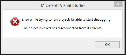
Odd. Start debugging again, and most of the time it will start without issue.
I’ve opened a bug report on Microsoft Connect: https://connect.microsoft.com/VisualStudio/feedbackdetail/view/982277/the-object-invoked-has-disconnected-from-its-clients
Issue 2: The Stub Manager…
Occasionally, also when starting debugging, I get the following error. Sometimes the error mentioned above in Issue 1 appears alongside, sometimes not:

Again, if I restart debugging for the application usually it will start without a hitch.
I’ve opened a bug report on Microsoft Connect: https://connect.microsoft.com/VisualStudio/feedbackdetail/view/982281/the-object-has-been-run-down-by-the-stub-manager-while-there-are-external-clients
Issue 3: Intellisense
Occasionally (I see a trend beginning to emerge here), Intellisense doesn’t sense. I have to type at least 2 characters of the Method, or Property or whatever, then delete one character. At this point, the matching member will appear.
This issue only appears occasionally – I’ve just tested it again to get a screenshot and of course, Intellisense worked fine.
Issue 4: There were (not) Build Errors.
Occasionally (definite trend established!), and this one is the most frustrating of the lot, Visual Studio 2013 will tell me that it can’t build the solution as there were errors. Except there are not. There’s nothing in the ‘Error List’, not even a warning.

Based on various forum suggestions I’ve tried ‘Run as Administrator’, and I’ve tried deleting the .suo user settings file. I have also tried also deleting the bin folder in the Solution folder but to no avail. Another suggestion was to turn on detailed output in Options -> Projects and Solutions -> Build and Run. This didn’t reveal anything. The only thing that works is restarting Visual Studio.
Here’s my Connect bug report: https://connect.microsoft.com/VisualStudio/feedbackdetail/view/982296/there-were-build-errors-when-building-a-solution-project
Help!
I won’t say that the above issues are ruining my experience with VS2013 Update 3, but they are little niggles that need to be ironed out. Also, I should mention that I wasn’t having any of the above issues with Update 2, however I was using that on Windows 8, not 8.1 which I am now using.
If anyone can shed any light on the above problems, then please let me know in the comments.

